Iranian Classification Society Rules

< Previous | Contents | Next >
Section 19 Air Pipe Automatic Closing Devices
1901. Application
The requirements in this Section apply to tests and inspection for the approval of air pipe auto- matic closing devices extending above weather decks in accordance with the requirements in Pt 5, Ch 6, 201. of the Rules.
1902. Design and Materials
1. Design of the air pipe automatic closing devices is to comply with the following requirements.
(1) An air pipe automatic closing device is to prevent the free entry of water into the tanks and allow the passage of air or liquid to prevent excessive pressure or vacuum coming on the tank. For vacuum, air pipe automatic closing devices are to be made for relieving vacuum in the tanks when the tanks are also being pumped out.
(2) The open ends of air pipes to fuel oil and cargo oil tanks are to be furnished with the flame-screens which can be readily removed for cleaning or renewal and deemed appropriate by the Society. The clear area through the mesh of the flame-screens is not to be less than the re- quired sectional area of the air pip
(3) Air pipe closing devices are to be designed so that they can withstand both ambient and work- ing conditions up to an inclination of ± 40° without failure or damage.
(4) Air pipe closing devices are to be constructed to allow inspection of the closure and the inside of the casing as well as for changing the seals.
(5) In case of air pipe closing devices of the float type, suitable guides are to be provided to en- sure unobstructed operation under all working conditions of heel and trim as specified in (3).
(6) Efficient ball or float seating arrangements are to be provided for the closures. Bars, cage or other devices are to be provided to prevent the ball or float from contacting the inner chamber in its normal state and made in such a way that the ball or float is not damaged when sub-
jected to water impact due to a tank being overfilled.
(7) Air pipe closing devices are to be self draining.
(8) The clear area through an air pipe closing device is to be at least equal to the area of the
inlet.
(9) The maximum allowable tolerances for wall thickness of ball floats are not to exceed ± 10 % of the nominal thickness.
(10)The inner and the outer chambers of an automatic air pipe head is to be of a minimum thick- ness of 6mm
2. Materials of the air pipe automatic closing devices is to comply with the following requirements.
(1) Casings of air pipe closing devices are to be of approved metallic materials adequately protected against corrosion.
(2) For galvanized steel air pipe heads, the zinc coating is to be applied by the hot method and the thickness is to be 70 to 100 m .
(3) For areas of the head susceptible to erosion (e.g. those parts directly subjected to ballast water impact when the tank is being pressed up, for example the inner chamber area above the air
pipe, plus an overlap of 10 degree or more either side) applied. This is to be an aluminium bearing epoxy, or
the zinc.
(4) Closures and seats made of non-metallic materials are to
an additional harder coating should be other equivalent, coating, applied over
be compatible with the media intended
to be carried in the tank and to sea water at ambient temperatures between -25 °C and 85 °C.
3. The flame-screens installed in automatic air pipe outlets are to comply with the following.
(1) They are to be made of corrosion resisting material.
(2) They are to comprise two fitted screens of at least 20 × 20 mesh spaced 25.4 ± 12.7 mm apart or single fitted screen of at least 30 × 30 mesh, or to have a performance equivalent thereto.
1903. Type tests
1. Testing of air pipe automatic closing devices
The following tests, specified in Table 3.19.1, for air pipe automatic closing devices by each type and size are to be carried out at the manufacturer's works or other acceptable location by the Society.
122 Guidance for Approval of Manufacturing Process and Type Approval, Etc. 2015
![]()
![]()
2. Impact and compression loading tests for the floats are to be carried out as specified in Table 3.19.2.
Table 3.19.1 Test methods and acceptance criteria for air pipe automatic closing devices
Kinds | Test Item | Type test method | Acceptance criteria |
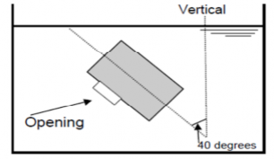
air pipe automatic closing devices | Tightness test | An automatic closing device is to be subjected to a series of tightness tests involving not less than two(2) immersion cycles under each of the following conditions. (1) The automatic closing device is to be submerged slightly below the water surface at a velocity of approximately 4 ml/min. and then returned to the original position immediately. The quantity of leakage is to be recorded. (2) The automatic closing device is to be submerged to a point slightly below the surface of water. The submerged velocity is to be approximately 8 m/min. and the air pipe vent head is to remain submerged for not less than 5 minutes. The quantity of leakage is to be recorded. (3) Each of the above tightness tests is to be carried out in the normal position as well as at an inclination of ± 40° under the strictest conditions for the device. In case where such strictest conditions are not clear, tests shall be carried out at an inclination of 40 degrees with the device opening facing in three different directions : upward, downward, sideways(left or right).(See Figure 3.19.1) | The maximum allowable leakage per cycle is not to exceed 2 ml/mm of nominal diameter of in- let pipe during any in- dividual test. |
Discharge/ Reverse flow thest | The air pipe head shall allow the passage of air to prevent ex- cessive vacuum developing in the tank. A reverse flow test shall be performed. A vacuum pump or another suitable device shall be connected to the opening of the air pipe leading to the tank. The flow velocity shall be applied gradually at a constant rate until the float gets sucked and blocks the flow. The veloc- ity at the point of blocking shall be recorded. 80% of the val- ue recorded will be stated in the certificate. | ||
Confirmation of the flow characteristic | Measuring of the pressure drop versus rate of volume flow is to be carried out using water and with any intended flame or insect screen in place. | To be as deemed appro- priate by the Society | |
non- metallic floats | Impact test | (1) The test may be conducted on a pendulum type testing machine. The floats are to be subjected to 5 impacts of 2.5 N-m each. (2) Subsequently the floats are to be subjected to 5 impacts of 25 N-m each. At this impact energy level some localized surface damage at the impact point may occur. | The floats are not to suffer either permanent deformation, cracking or surface deterioration at this impact loading. |
Compression loading test | (1) Compression tests are to be conducted with the floats mounted on a supporting ring of a diameter and bearing area corresponding to those of the valve seating with which it is intended that float shall be used. (2) For ball type float, loads are to be applied through a con- cave cap of the same internal radius as the test float and bearing on an area of the same diameter as the seating. (3) For a disc type float, loads are to be applied through a disc of equal diameter as the float. (4) A load of 350 kg is to be applied over one minute and maintained for 60 minutes. The deflection is to be meas- ured at intervals of 10 minutes after attainment of the full load. | The record of deflection against time is to show no continuing increase in deflection and, after release of the load, there is to be no perma- nent deflection. | |
metallic floats | Impact test | Tests are to be conducted in accordance with the impact test of non-metallic floats. The tests are to be carried out at room temperature and in the dry condition. | according to the require- ment for impact test of non-metallic floats. |
Guidance for Approval of Manufacturing Process and Type Approval, Etc. 2015 123
![]()
![]()
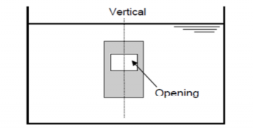
(1) normal position
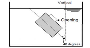
(2) inclination 40 degree opening facing upward
(3) inclination 40 degree opening facing downward
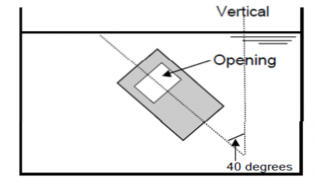
(4) inclination 40 degree opening facing sideways Fig 3.19.1 Example of tightness test
124 Guidance for Approval of Manufacturing Process and Type Approval, Etc. 2015
![]()
![]()
![]()
Table 3.19.2 Temperature and Condition of Test
Test temperature (°C) Test condition | -25 | 20 | 85 |
Dry | ○ | ○ | ○ |
After immerging in water | ○ | ○ | ○ |
After immerging in fuel oil | ○ | ||
NOTES: 1. Type tests are to be performed for each test item indicated with a ○ mark in this Table. 2. Immerging in water and fuel oil is to be for 48 hours at least. | |||
Guidance for Approval of Manufacturing Process and Type Approval, Etc. 2015 125
![]()
![]()